Hardware Improvements
Let’s imagine you write a script to turn on a light bulb. At first glance, nothing happens. Should you rewrite the code? Often, the simplest approach is to check whether the bulb is properly plugged in.
This guide follows the same philosophy. Before troubleshooting software issues or motor-control logic, you should first ensure that the mechanical parts of the chassis are functioning optimally.
Below you will find recommendations for mechanical improvements, adjustments, and common checks that help prevent unnecessary debugging.
FAQ
What are the advantages?
Improving mechanical skills
Reducing friction in the transmission (lower current consumption)
Achieving smoother driving
Reducing the risk of the car getting stuck while cornering
Can this step be skipped?
The car kit includes a brushless motor with an integrated ESC, which maintains a nearly constant speed. This compensates partially for drivetrain friction and helps avoid getting stuck. However—just like buying a used car—it is strongly recommended to perform a mechanical inspection to ensure optimal performance.
What tools do I need?
Hex key screwdriver
Grease
Degreaser
Isopropyl alcohol
Sponge & brush
Pliers
Phillips screwdriver
Flat file / sandpaper

How much time is needed?
Approximately 4 hours of work.
Transmission from the Motor
This part includes:
Cleaning and greasing both differentials
Adjusting distances when remounting components
Checking for friction throughout the drivetrain
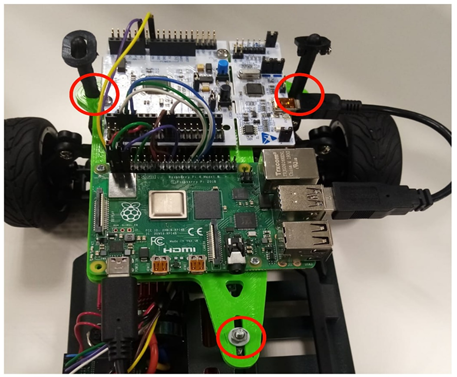
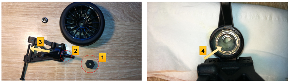
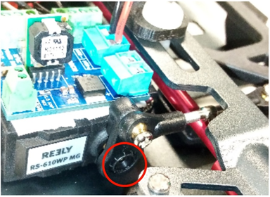
Removing the Computer Board Support
Disconnect all wires, remove the mounting nut, then take off the safety clamps and case holders.
Removing the Back Driving Shafts
Unscrew the highlighted screws:
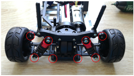
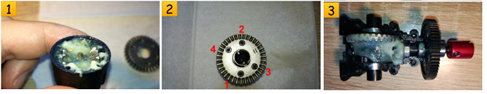
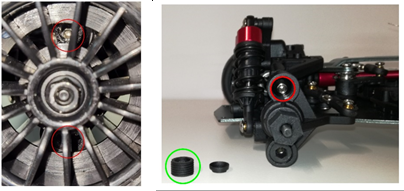
Removing the Differential
Unscrew the highlighted screws. After step 3 you will see the cogwheels.

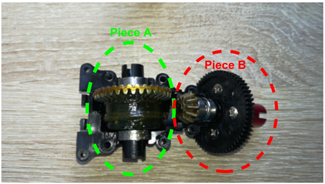
Cleaning the Cogwheels
Remove both differential halves. From Piece A, remove the bearing and permanently remove the washer.
Clean all grease from the case, cogwheels, and bearings. Degrease the bearings thoroughly (e.g., with isopropyl alcohol) until they spin freely.
Tightening the Screws Equally
Remove the safety washer (A), then permanently remove the washer (B).
Remove the screws from the plastic cogwheel. Lightly sand the surface where the flange attaches until flat.
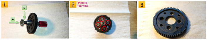
Mounting Them Back
Apply grease to all moving parts.
Tighten screws evenly (not too tight), in the order indicated.
Spin the driving shaft to verify there are no blocking points.
Adjusting the Distance Between Cogwheel Axes
Because cogwheels are not perfectly round, the gap between them may change during a full rotation. This may cause:
Loss of grip
Wheel locking
Procedure:
Loosen screw C
Have someone spin both front wheels while you adjust the cogwheel distance
The goal is smooth rotation throughout the entire revolution of cogwheel A
Note: tightening screw C may shift the cogwheel, requiring re-adjustment.

Front-Axis Differential
The front differential requires exactly the same treatment as the rear one.
Abnormal Free Movement of the Wheels
It is normal for wheels to feel slightly loose. You must balance:
Too much freedom → loose parts
Too much stiffness → restricted movement
We recommend placing a thin washer between the bearing and the driving shaft joint (thickness depends on the gap). Compare the modified wheel with an unmodified one.
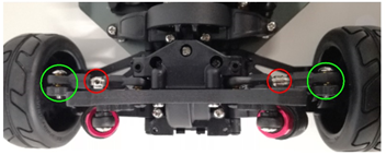
Driving Shafts Must Move Freely
The highlighted parts are the driving shafts. They must always move freely, regardless of wheel angle or ground clearance.
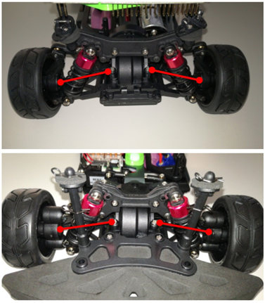
To increase free movement:
Slightly unscrew both the upper and lower screws
Repeat until the shaft moves freely in all positions
Steering
The steering servo requires an additional screw to ensure the steering column does not disengage. The placement is difficult to access when the car is fully assembled.
Possible options:
Install it while working on the front differential.
Unscrew the servo (without removing the rod), install the screw, and then reassemble.
Use an improvised angled screwdriver—best for patient users.
Important: Ensure the Nucleo and servo are powered so that the servo holds the 0° position during installation.
Setting the Wheels’ Camber
What is wheel camber?
Camber is the angle of the wheel relative to a flat surface:
Positive camber: top of wheel leans outward
Negative camber: top leans inward
For this challenge, a negative camber is recommended.
Benefits:
Improved handling
Reduced vibration during turns
Higher cornering speeds
More direct steering
Reduced steering force
Smaller steering angles
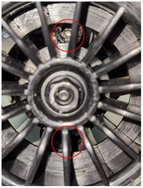
### Setting Front-Axle Camber
Two ball-head screws (red circled) control camber. Steps:
Insert a 2.5 mm hex wrench through the wheel rim
Unscrew the upper screw more than the lower one
Adjust both sides symmetrically
When removing the wheel, you will see a plastic grub screw (green circled), tightened with a 5 mm hex wrench. This only secures the axis stub.
Before reattaching the wheel:
Ensure both ball-head screws rotate freely
Ensure suspension moves freely after adjustment
### Setting Rear-Axle Camber
You can modify rear camber by:
Turning the red-circled screws to change the distance between chassis and wheel top
OR adjusting the traverse link mounting position (three available holes, green circled)
Setting the Wheels’ Alignment
What is wheel alignment?
Alignment (toe-in / toe-out) describes how the wheels point relative to the driving direction.
Toe-in is recommended for this challenge:
Improves lateral cornering
Gives more direct steering response
### Setting Front-Axle Alignment
Turn the track rod levers (red circled). They have reverse threads and can be adjusted without disassembly. Ensure both sides are adjusted symmetrically and test that the car drives straight.
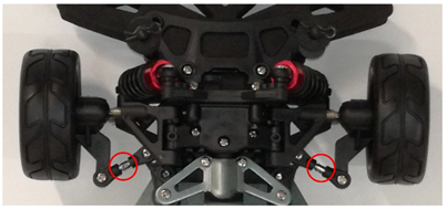
Adjusting the Car’s Height
Ground clearance is set using four screws. To increase height, loosen them (do not remove them).
Screw locations:

Adjusting the Suspensions
Even after increasing clearance, the car may not stay elevated due to soft suspension springs.
Suspensions can be hardened by: - Using one of six possible combinations - Adding a spacer between the spring and its support
