Calibration
This page explains how to integrate the calibration results generated by the dashboard into the Embedded project and what happens internally once the new calibration sources are added to the firmware.
Overview
The dashboard generates a set of C++ source files that contain updated polynomial
coefficients, steering offset values, spline data points, and speed/steer correction
tables. These files replace the previous calibration implementation inside the
Embedded_Platform project.
During firmware build, the embedded code automatically incorporates the new calibration parameters and uses them at runtime for:
Translating steering commands into corrected wheel angles
Adjusting motor speed using the updated polynomial mapping
Applying the zero-offset correction obtained during calibration
Improving trajectory accuracy using the newly generated splines
No manual editing of the source code is required — only copying the generated
source folder into the correct location.
Internal behavior
The generated archive contains a source folder with two files:
speedingmotor.cppsteeringmotor.cpp
These files already exist in the Embedded_Platform project. When you copy the
new versions over the existing ones, the firmware behavior is updated as follows.
Calibration flags and limits
Both files define a common calibration configuration:
#define calibrated      0
#define calib_sup_limit 500
#define calib_inf_limit -500
In the default Embedded_Platform sources:
calibratedis set to0(calibration disabled)calib_sup_limitandcalib_inf_limituse generic default bounds
In the generated files:
calibratedis set to1to enable the calibrated behaviorcalib_sup_limitandcalib_inf_limitare updated with the limits computed during the calibration process
These limits are used to clamp the output of the control logic to safe ranges.
Polynomial-based control
Both speedingmotor.cpp and steeringmotor.cpp implement a
computePWMPolynomial method. In the default sources this function only contains
a placeholder:
int CSpeedingMotor::computePWMPolynomial(int speed)
{
    int64_t y = zero_default;
    // POLYNOMIAL CODE START

    // POLYNOMIAL CODE END
    return (int)y;
}
The generated files fill in this method with the polynomial expression obtained during calibration. The polynomial maps the requested speed or steering angle to a PWM value, using the calibration data captured on the track.
Runtime selection: calibrated vs. legacy behavior
The motor classes expose high-level setters such as setSpeed (for the speed
motor) and setAngle (for the steering motor). Their structure is similar to:
void CSteeringMotor::setAngle(int f_angle)
{
    pwm_value = zero_default;

    if (calibrated == 1)
    {
        pwm_value = computePWMPolynomial(f_angle);
    }
    else
    {
        pwm_value = interpolate(f_angle,steeringValueP, steeringValueN, pwmValuesP, pwmValuesN, 3);
    }

    m_pwm_pin.pulsewidth_us(pwm_value);
}
When
calibrated == 0(default firmware), the code uses the legacy interpolation tables (interpolate(...)and pre-defined lookup arrays).When
calibrated == 1(after copying the generated files), the firmware switches to the polynomial model by callingcomputePWMPolynomial(...).
As a result, once the new speedingmotor.cpp and steeringmotor.cpp are copied
and the firmware is rebuilt and flashed, all speed and steering commands are
translated using the newly calibrated polynomial models and updated limits, rather
than the generic factory interpolation curves.
Steps
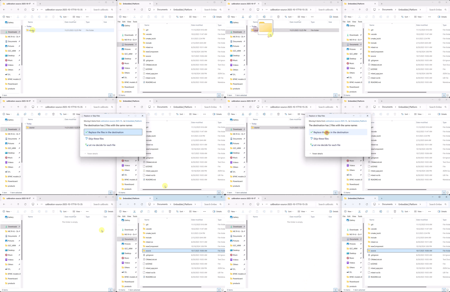
Step 1. Extract the archive
Locate the downloaded file (e.g.
calibration-source-2025-10-17T10-15-35.zip).Extract the archive to a temporary location.
After extraction, you should see a folder named
source.
Step 2. Copy the calibration source folder
Open the extracted contents.
Copy the
sourcefolder.Paste it into the
Embedded_Platformdirectory of your Embedded project (example:<project-root>/Embedded_Platform).If asked to overwrite existing files, choose Replace.
After this step, the firmware project will contain the latest calibration sources. These files will automatically be compiled and linked during the next build.

Step 3. Build and flash
Flash the firmware to the vehicle by following the instructions in the Build & Flash Guide.
Once flashing is complete, the vehicle will run using the newly generated calibration model (steering, speed, and offset corrections).