IMU
The BFMC car uses a 9-DoF absolute orientation sensor based on the Bosch BNO055. Across the years, three revisions of the IMU board were produced, all electrically compatible and using the same sensor.
Available IMU board versions

All boards contain the BNO055 module (3-axis accelerometer, 3-axis gyroscope, 3-axis magnetometer, with on-chip sensor fusion).
The pinout is identical between versions:
+5V/VIN: IMU supply input
GND: Ground
RST: IMU reset pin (active low)
INT: Interrupt output (optional)
ADR: I2C address selection
SCL: I2C clock
SDA: I2C data
IMU specifications
Sensor: Bosch BNO055
Fusion algorithm: On-chip 9-DoF fusion (NDOF mode)
Communication interface: I2C
- Default I2C address:
0x28 when ADR = GND
0x29 when ADR = 3V3
Supply voltage: 5V input, regulated on-board to 3.3V
I/O voltage levels (I2C, INT, RST): 3.3V
Typical current consumption: ~12–15 mA
Output data rate: configurable (typically 100 Hz recommended for BFMC)
Operating notes
The IMU should be mounted rigidly and as close as possible to the vehicle’s center of rotation.
For best performance, the NDOF fusion mode is recommended.
Before starting the run, allow a few seconds for the internal fusion to stabilise.
- The INT pin can be used for:
data ready interrupt
fusion event interrupt (optional)
The RST pin can be used to manually reset the sensor if needed.
How to connect your IMU (per board)
All boards use the same BNO055 sensor and are electrically compatible, but the connector pin labels differ slightly between versions.
Please identify your board below and follow the corresponding wiring diagram.
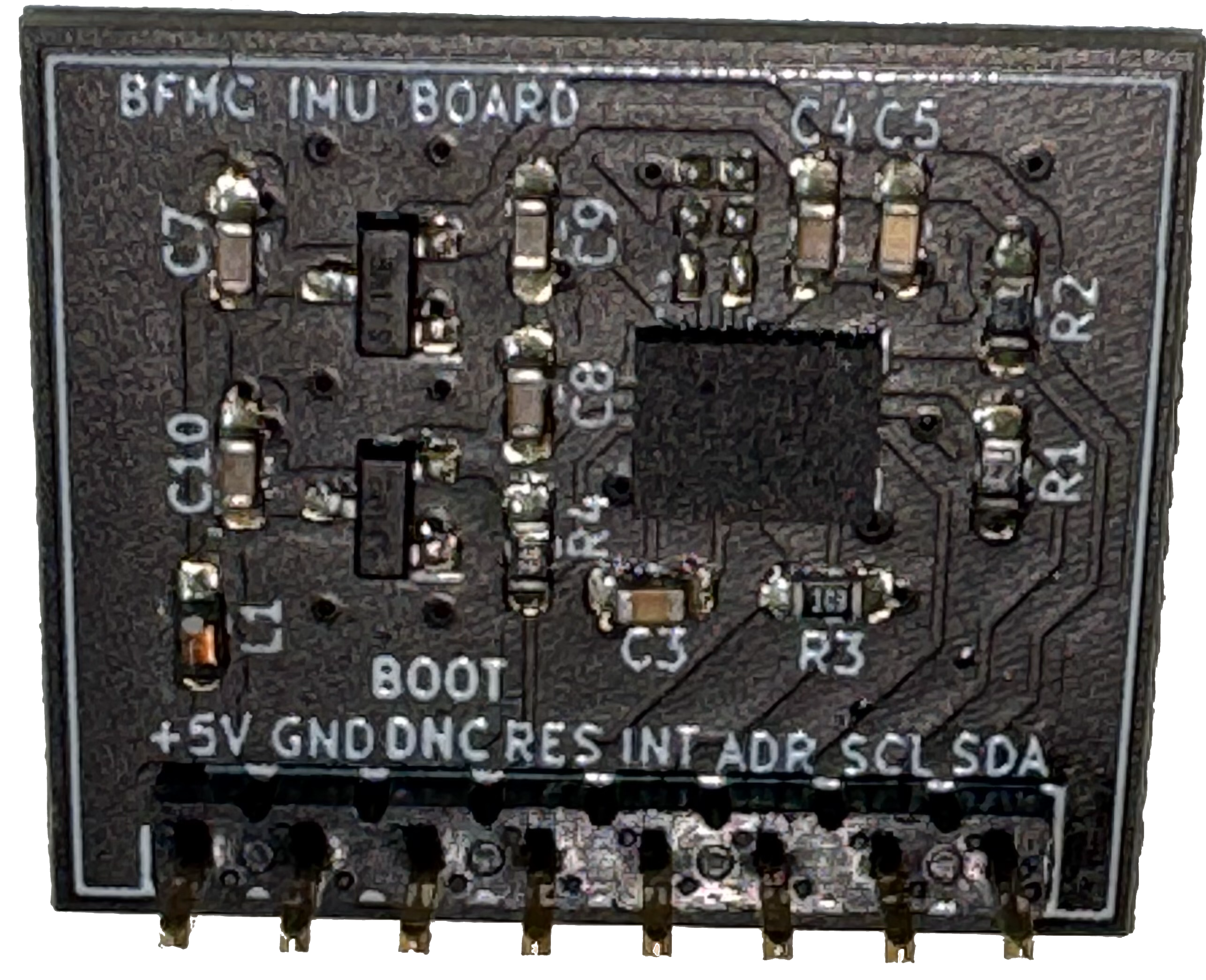
Board A
Pin mapping (from left to right):
+5V: IMU supply input
GND: Ground
SCL: I2C clock
SDA: I2C data
INT: I2C address selection (ADR)
ADR: Interrupt output (INT)
RST: IMU reset (active low)
Warning
This revision uses a different silkscreen convention for the INT and ADR pins. Functionally the signals are identical to newer versions; only the printed labels differ.
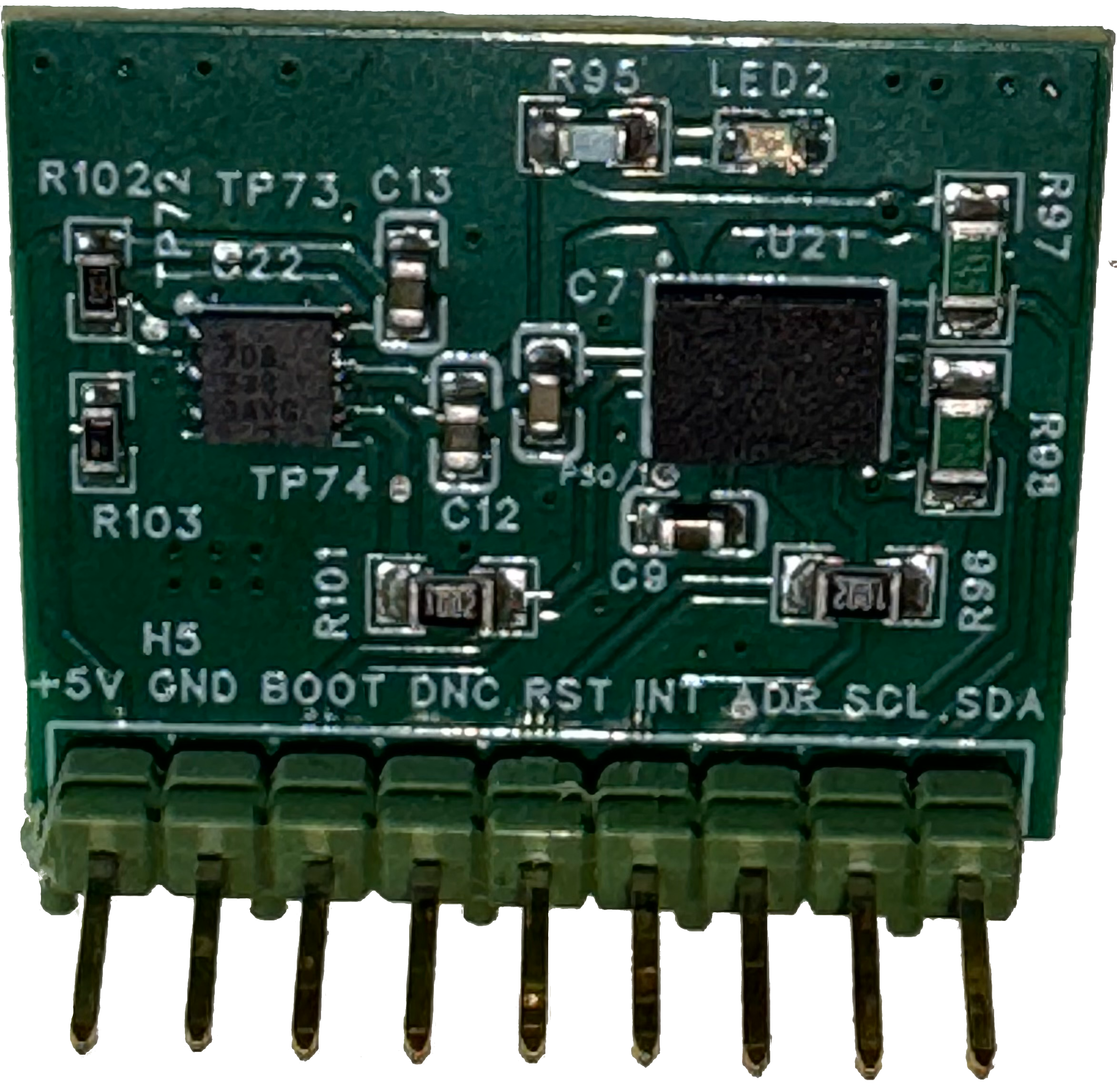
Board B
Pin mapping (from left to right):
+5V: IMU supply input
GND: Ground
BOOT: Boot mode pin (unused in normal operation)
DNC: Do not connect
RST: IMU reset (active low)
INT: Interrupt output (optional)
ADR: I2C address selection
SCL: I2C clock
SDA: I2C data
Board C
Pin mapping (from left to right):
+5V: IMU supply input
GND: Ground
BOOT: Boot mode pin (unused in normal operation)
DNC: Do not connect
RST: IMU reset (active low)
INT: Interrupt output (optional)
ADR: I2C address selection
SCL: I2C clock
SDA: I2C data
Tip
Address select also available via shorting the solder jumper on the back of the board: